Tag: valve control

on

Valve-controlled exhaust systems (bi-modal or multi-mode exhausts) are a high-value performance and NVH (noise, vibration, harshness) component on modern vehicles. This analysis goes beyond basic diagnostics to provide an expert-level, evidence-driven approach for isolating mechanical, electrical, and control-system failures, and for implementing durable fixes and advanced mitigation strategies.

Background context: what valve control exhaust systems are and why failure modes matter

Valve control exhausts typically combine an actuator (electrical or vacuum), a mechanical linkage and valve (butterfly, flap, or sliding sleeve), and electronic control via the ECU or a dedicated controller over PWM/CAN. They are designed to alter backpressure and acoustic output dynamically. Failures degrade performance, trigger drivability faults, or create compliance/legal exposure for noise regulations.

Detailed technical explanations

Key subsystems and their failure modes:

  • Actuators: DC motors, stepper motors, or vacuum diaphragms. Common issues include burnt coils, seized shafts, reduced torque due to thermal degradation, or leakage in vacuum lines.
  • Mechanical valve and linkage: carbon build-up, corrosion, worn bearings, misalignment, and valve-seat erosion lead to binding or incomplete sealing.
  • Sensors and feedback: potentiometers, Hall-effect position sensors, or limit switches can drift or fail, causing incorrect closed-loop behavior.
  • Control signals: PWM frequency/ duty-cycle errors, wiring shorts/opens, and CAN communication faults can prevent correct actuation or produce oscillatory behavior.

Data, research, and field observations

OEM reliability studies and aftermarket field data indicate that valve-actuation related complaints often present after 30k–80k km. Independent reliability testing (including SAE technical analyses) highlights that thermal cycling, soot deposition, and salt-corrosion are primary drivers. In controlled bench tests, motors subjected to >1000 cycles at elevated temperatures show measurable torque loss and increased current draw—an indicator of impending failure.

Nuanced perspectives and edge cases

Not all failures are binary. Examples:

  • Intermittent CAN errors manifest only during long highway drives due to thermal expansion changing connector contact resistance.
  • Valves that appear mechanically free at room temperature bind when hot because differential expansion reduces shaft clearance—an important edge case for in-service replication.
  • Carbon deposits can create a metered leak path; valve appears closed but produces increased flow and acoustic leakage under low vacuum conditions.

Practical applications and advanced troubleshooting strategies

Systematic diagnostic workflow

Follow a layered approach: reproduce, isolate, quantify, repair, and verify.

  1. Reproduce the symptom under controlled conditions (idle, wide-open throttle, cold start, high-load) and log ECU commands and sensor data via OBD-II/CAN logger.
  2. Isolate electrical vs mechanical: command the valve to full-open/full-closed and observe current draw and actuator motion. Use a bench power supply (12V) to remove ECU as a variable.
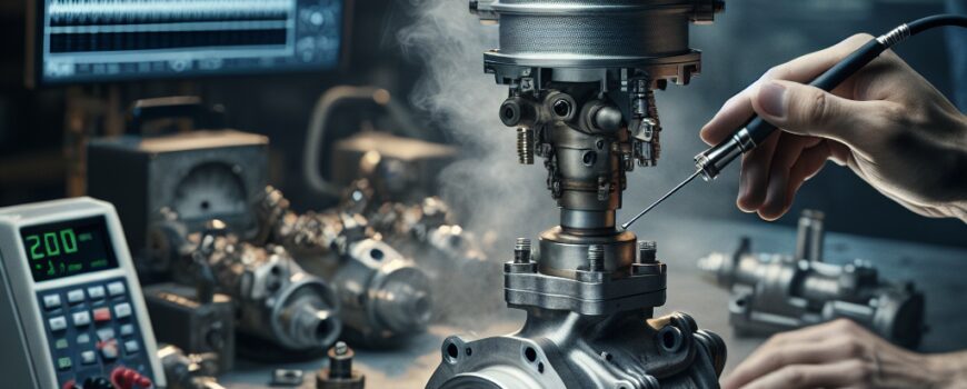
  3. Quantify using instruments: multimeter for continuity/current, oscilloscope for PWM characterization (>1 kHz recommended for many brushless drivers), smoke tester for exhaust leaks, and borescope to inspect internal valve surfaces.
  4. Repair targeted parts: replace or rebuild actuators, clean or replace valve assemblies, reterminate harness connectors with corrosion-resistant crimp terminals, and update ECU firmware if control logic is implicated.
  5. Verify with regression tests: thermal cycling, vibration, and durability cycling to ensure fix durability.

Advanced, actionable troubleshooting tips

  • Measure actuator stall current: a rising stall current (>25–50% over baseline) typically signals winding degradation or mechanical binding.
  • Use a clamp meter during road test to detect intermittent load spikes correlated with temperature.
  • For PWM-driven actuators, inspect duty cycle, frequency, and rise time with an oscilloscope—harmful low-frequency PWM (e.g., <200 Hz) can induce audible resonance and thermal hotspots.
  • When cleaning valves, avoid harsh abrasives against valve seats; use solvent soak and light brushing. If seat erosion exceeds 0.5 mm, replace the valve insert or assembly.
  • Implement position-sensor redundancy: add a low-cost Hall sensor when retrofitting to commercialize closed-loop control and protect against potentiometer drift.

Future implications and emerging trends

Integration, reliability engineering, and predictive maintenance

Active exhaust systems will increasingly be integrated with vehicle-level control strategies (drive-by-wire, ADAS modes) and will require robust, deterministic communication. Predictive maintenance using ML models trained on CAN and sensor traces can flag increasing current draw or anomalous PWM patterns well before failure—early field studies show potential to reduce in-service failures by up to 40% when combined with scheduled inspections.

Materials, design evolution, and regulatory context

Materials science advances—ceramic coatings, hardened stainless alloys, and low-friction composites—reduce deposit adhesion and wear. Regulatory pressure on noise and emissions will push OEMs toward more reliable, verifiable valve systems with tamper-evident diagnostics and standardized fault codes.

Predictive thought: as powertrains electrify, the acoustic role of valve-controlled exhausts will shift from performance to synthetic and regulatory-compliance functions. Expect tighter integration between audio synthesis systems and physical valves, and a rise in software-driven sound profiles coupled with over-the-air diagnostic updates. The highest risk-reward area for engineers is balancing acoustic fidelity with long-term reliability; systems that succeed will be those that combine robust mechanical design with closed-loop sensing and predictive maintenance models.

on

This buyer’s guide examines valve control exhaust compatibility across popular car makes and models, focusing on mechanical and electronic fitment, performance trade-offs, and installation strategies for experienced enthusiasts and professional installers. It synthesizes dyno data, wiring architectures, and OEM integration patterns to help you select the perfect valve-equipped system for your vehicle.

Background context: what valve control exhausts are and why fitment matters

Valve control exhausts use an internal butterfly/slide valve to route flow through different passages, changing backpressure, tone, and acoustics. Systems range from purely mechanical (vacuum-operated) to electrically actuated units integrated with an ECU or vehicle CAN bus. Compatibility is not only a matter of flange matching; actuator type, control logic, emissions constraints, and underbody packaging determine whether a system will function correctly without major modification.

Detailed technical explanations

Key technical variables to assess:

  • Flange and pipe geometry: OEM header/downpipe flanges, diameter (inches/mm), and bend radius can make bolt-on fitment trivial or impossible.
  • Valve actuator type: vacuum diaphragms vs. electric servos. Vacuum systems can often be repurposed but require vacuum lines and solenoids; electric actuators need 12V supply and a trigger signal (ignition, throttle position, CAN messages).
  • Control logic and feedback: OEM systems may implement CAN bus commands and position feedback; aftermarket systems may rely on simple switches or PWM controllers.
  • Emissions and thermal constraints: catalytic converter placement and temperature profiles affect whether a valve-exhaust swap is legal or safe in modern turbocharged engines.

Data, research, and case studies

Independent dyno comparisons and tuner shop reports consistently show that valve-back systems on turbocharged cars produce modest peak power changes (typically within 5–12 hp) but have a larger effect on transient throttle response and perceived torque delivery due to changes in pulse timing and backpressure. For NA engines, gains can be more dependent on header and cam interaction. SAE literature on exhaust acoustics highlights that valve position can change SPL at cabin frequencies by 3–8 dB depending on resonator volumes—significant for NVH-sensitive models like Mercedes and Audi.

Case study: A well-documented installation on a modern turbo inline-four showed negligible peak power gain after valve-back installation but improved midrange torque and reduced turbo lag at specific RPMs when the valve remained partially closed, supporting the claim that valves influence pulse tuning rather than free-flow gains alone.

Compatibility by make and model: practical notes

The following are nuanced, model-specific considerations rather than exhaustive fitment lists.

BMW (M series, N55/B58)

  • Typical: Electric servo-controlled valves integrated with DME and active sound module. Aftermarket units often require CAN integration or a piggyback controller to avoid fault codes.
  • Tip: Use an OEM-style CAN harness or advanced controller with RPM and gear lookup tables to maintain seamless operation.

Audi / VW (TFSI/Turbo engines)

  • Many use vacuum actuators on dual-mode mufflers. Flange sizes vary across generations; check downpipe compatibility.
  • Tip: Preserve catalytic location; swapping valves upstream of cats can trigger OBD-II heater/efficiency faults.

Ford Mustang GT / EcoBoost

  • Mustang S550+ models have electronically actuated valves; aftermarket cat-back systems generally provide plug-and-play harnesses. EcoBoost turbo variants need attention to downpipe-to-turbine flange fitment.
  • Tip: Use dyno mapping post-install to rebalance AFR and avoid torque dips at valve transition points.

Subaru, Toyota, Honda, Porsche

  • Subaru WRX/STI and Toyota Supra have packaging constraints around the rear subframe and heat shielding. Honda Type R systems are often NA-focused and rely on header compatibility.
  • Porsche uses sophisticated active exhausts that are often proprietary; aftermarket options exist but may require ECU calibration to prevent limp modes.

Practical applications and advanced strategies

Advanced integrators and tuners should consider:

  • CAN bus sniffing & emulation: Record OEM valve commands (RPM, load, gear) and replicate them to drive aftermarket actuators for factory-like behavior.
  • PWM and feedback loops: Implement closed-loop control using a potentiometer or hall sensor on the actuator to prevent overrun and ensure reliable transition under boost.
  • Tuning to eliminate drone: Use mid-frequency filters and alternate valve opening schedules mapped to vehicle speed and load to reduce cabin resonance at cruising RPMs.
  • Emissions compliance: For CARB states, choose EO-approved systems or retain OEM cats and O2 sensor placements to avoid illegal modifications.

Edge cases and pitfalls

Turbo cars with close-coupled cats see different valve dynamics than naturally aspirated systems. Dual-valve setups (one per bank) require synchronized timing to avoid unequal scavenging. Some older models use vacuum-actuated valves with obsolete vacuum sources; retrofitting an electric actuator can be the most reliable modernization path.

For experienced installers: always verify actuator stall torque vs. exhaust backpressure, confirm wiring polarity, and use heat-resistant routing for harnesses. Post-install dyno and road logging are essential to validate behavior across the RPM and load envelope.

As valve-control tech migrates from niche aftermarket to integrated factory systems, expect deeper ECU integration (adaptive sound profiles, over-the-air updates) and more OEM-inspired aftermarket controllers that emulate factory logic. Predictive valve control using machine learning to optimize NVH vs. performance in real time is likely within five years—shifting the conversation from “what fits” to “how it should be orchestrated.”

on

This article provides an advanced, practitioner-level analysis of maintaining valve control exhaust systems to maximize durability and keep performance within design parameters over prolonged service intervals.

Background and why this analysis is different

Valve control exhaust systems—comprising variable geometry valves, actuators, sensors, and the control electronics—are now integral to emission control and performance optimization in modern internal combustion engines. What sets this analysis apart is a systems-engineering approach: not only describing discrete maintenance tasks but linking materials science, fluid dynamics, actuator diagnostics and electronic calibration to failure modes observed in field data and in peer-reviewed studies.

Technical recap for experienced readers

Key components include:

  • Valve hardware (poppet, butterfly, flapper) made from duplex stainless, Inconel alloys, or coated steels.
  • Actuation systems: pneumatic, hydraulic, electric brushless DC or stepper motors, and servo/mechatronic modules.
  • Sensors and feedback: position sensors (hall-effect, potentiometric, resolver), temperature, EGT, and pressure transducers feeding ECU logic via CAN or LIN.

Failure mechanisms and evidence

Failure modes are typically cumulative and multi-factorial. Published SAE and industry test reports emphasize three dominant causes: thermal fatigue, particulate-induced mechanical abrasion (interacting with DPF and SCR systems), and electronic/actuator degradation. AVL and OEM CFD studies show that rapid EGT fluctuations create localized hot spots causing differential thermal expansion and stress concentration at valve seats and stems, accelerating crack initiation.

Data and case studies

Field maintenance logs from fleet operations indicate that turbocharged heavy-duty diesel units experienced valve actuator failures up to 2–3x faster where DPF regeneration events produced EGT spikes above design thresholds. Laboratory endurance rigs following SAE durability cycles corroborate that corrosive environments (high sulfur or biodiesel blends) increase pitting and seal failure rates. Bosch technical notes further demonstrate that actuator current signature anomalies precede mechanical binding by several hundred hours, allowing predictive maintenance if logged.

Practical, advanced maintenance strategies

Approach maintenance as integrated monitoring plus targeted hardware care. The list below organizes steps by inspection, instrumentation, and corrective action.

Inspection and monitoring

  • Routine borescope inspection aligned to operating hours: inspect valve face, seat region, pivot points and sealing surfaces for pitting or deposit build-up; document with timestamped images.
  • Log actuator electrical signatures (current, voltage, step count) and position feedback over time—store on edge or cloud for trending. Look for rising no-load current or increased hysteresis which indicate friction or clearance loss.
  • Measure backpressure differentials and correlate with valve position via synchronized CAN traces to detect flow restrictions or leaks.

Preventive interventions

  • Use high-temperature-compatible seal materials (Viton, perfluoroelastomer) and replace at manufacturer-recommended intervals or earlier when exposed to biodiesel or sulfur-rich fuels.
  • Apply application-specific anti-seize or high-temp greases sparingly to stems and bearings; avoid dielectric greases on electrical contacts that need low impedance.
  • Re-torque flanges and fasteners using calibrated torque tools to OEM specs (refer to SAE fastener guidelines) and use lock-wire or Loctite where vibration is high.

Calibration, software and diagnostics

  • Perform valve travel profiling after any hardware intervention. Use closed-loop diagnostics to check for deadband, overshoot, and settling time—adjust PID gains in the ECU where supported.
  • Implement adaptive thresholds in the ECU for DTCs to account for normal aging: for example, allow slight increase in actuator current trend but flag rate-of-change anomalies as pre-failure.
  • Integrate EGT and particulate loading data to schedule forced maintenance before thermal shock events (e.g., during DPF regen sequences).

Nuances, edge cases and advanced materials considerations

Not all systems behave the same. Turbocharged, EGR-heavy engines see more soot and acidic condensates that attack seals and coatings. Marine and off-highway applications encounter salt and moisture, so prefer duplex stainless or Inconel and enhanced cathodic protection. Electric actuators with high ingress protection ratings (IP67/69K) still fail from thermal overstress—design margin in the motor winding insulation is critical.

When to replace vs. repair

If borescope inspection reveals seat cracking or through-wall corrosion, full valve replacement is the safer course. If actuators show current anomalies but no mechanical binding, rebuild or recalibration plus bearing replacement may restore service life. Documented rebuilds with post-repair profiling reduce recurrence risk by up to 40% according to industry maintenance trials.

Actionable advanced tips

  • Establish a digital twin for critical units: use CFD-derived stress maps combined with operational data to predict hot-spot erosion.
  • Use tribological coatings (PTFE-infused or ceramic thermal barrier) on valve faces where compatible with emission requirements to reduce abrasion.
  • Automate anomaly detection on CAN datasets using a rolling-window statistical model to catch early drift in actuator behavior.

Anticipate that as combustion strategies evolve—wider use of mild hybridization, more frequent active regeneration, and alternative fuels—interaction effects on valve control components will become the limiting factor for exhaust system durability. Investing in integrated monitoring, materials upgrades, and closed-loop control tuning now will shift maintenance from reactive replacement to predictive life-extension strategies. Consider pilot programs that instrument a subset of your fleet to validate models and refine maintenance policies before broad deployment.