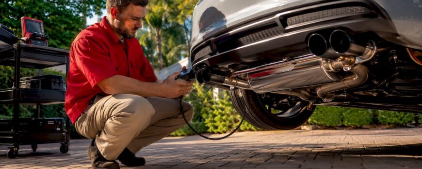
Exhaust diagnostic tools verify combustion quality, backpressure, and valve-actuator function so your valved exhaust delivers the power and sound you actually paid for. Before you touch a wrench, three tools matter most: a wideband O2 meter, a backpressure gauge, and a scan tool. Log a stock baseline with all three, install your system, then verify against those numbers. Valvecontrolexhaust builds this workflow into every product release through dyno validation and documented valve-motor testing, so you have a reference point from day one.
- Wideband O2 / lambda meter: captures air/fuel ratio across the rev range
- Backpressure gauge: quantifies physical restriction at the O2 bung
- Scan tool / datalogger: reads live OBD-II data and stores runs for comparison
- Exhaust gas analyzer: confirms combustion chemistry beyond what OBD codes show
- Dyno: the only tool that validates claimed power and torque under repeatable load
OBD-II systems flag emission-related deterioration and store codes — but the Check Engine light is a warning, not a diagnosis. Every code needs follow-up testing to confirm root cause.
Table of Contents
- What role do exhaust diagnostic tools play in performance builds?
- Why valved exhausts demand a combined diagnostic approach
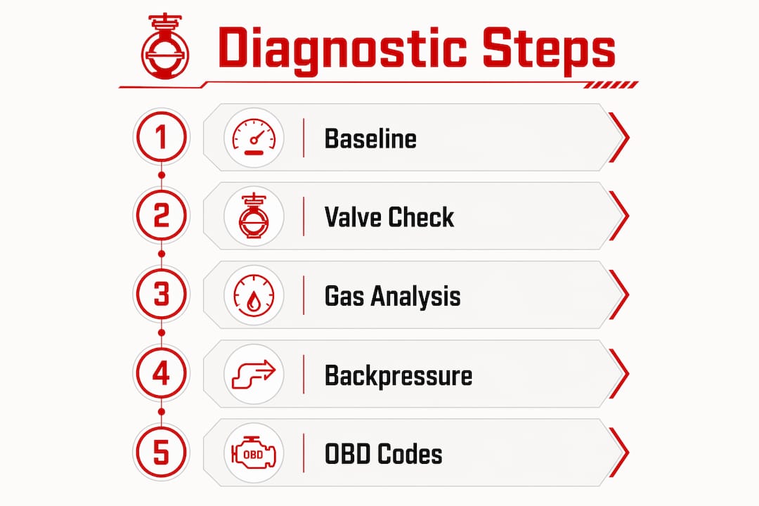
- How to run a diagnostic workflow for a valved exhaust install
- How to read common diagnostic outputs and avoid misdiagnosis
- When can you run these tests yourself, and when should you call a shop?
- How Valvecontrolexhaust validates systems before they reach you
- Key Takeaways
- What most guides get wrong about exhaust diagnostics
- Valvecontrolexhaust: dyno-tested systems built for your build
- Authoritative sources used in this article
What role do exhaust diagnostic tools play in performance builds?
The six tools below cover every layer of exhaust system analysis, from combustion chemistry to physical restriction. Each one answers a different question; none of them alone tells the full story.
| Tool | What It Measures | Why It Matters for Valved Exhausts |
|---|---|---|
| Wideband O2 / lambda meter | Air/fuel ratio across the rev range | Detects lean/rich shifts caused by flow changes after valve install |
| Exhaust gas analyzer (FTIR/NDIR) | CO, CO2, HC, NOx concentrations | Reveals combustion inefficiency that OBD data can miss; FTIR/NDIR methods enable continuous monitoring |
| Backpressure gauge | Pressure at the O2 bung under load | Quantifies restriction; compare idle vs. 2,500 rpm readings |
| Scan tool / datalogger | OBD-II codes, MAF, MAP, calculated load | Stores runs for before/after comparison; starting point for any fault |
| Dyno with data logging | Power, torque, valve position behavior | Only practical method to validate claimed gains under controlled load |
| Smoke / leak tester | Exhaust leaks at joints, gaskets, flanges | Finds leaks that skew O2 and sensor readings before they mislead you |
A quick exhaust gas analyzer check can confirm mechanical inefficiency that electronic monitoring masks entirely. Shops that skip the analyzer and rely only on scan-tool codes regularly misdiagnose the root cause.
Why valved exhausts demand a combined diagnostic approach
A valved system changes flow path and backpressure dynamically depending on valve position. That shift can trigger OBD sensors and alter fueling or ignition timing, especially on turbocharged platforms where boost and exhaust flow are tightly coupled. The result: a perfectly installed system can throw codes that look like sensor failures.
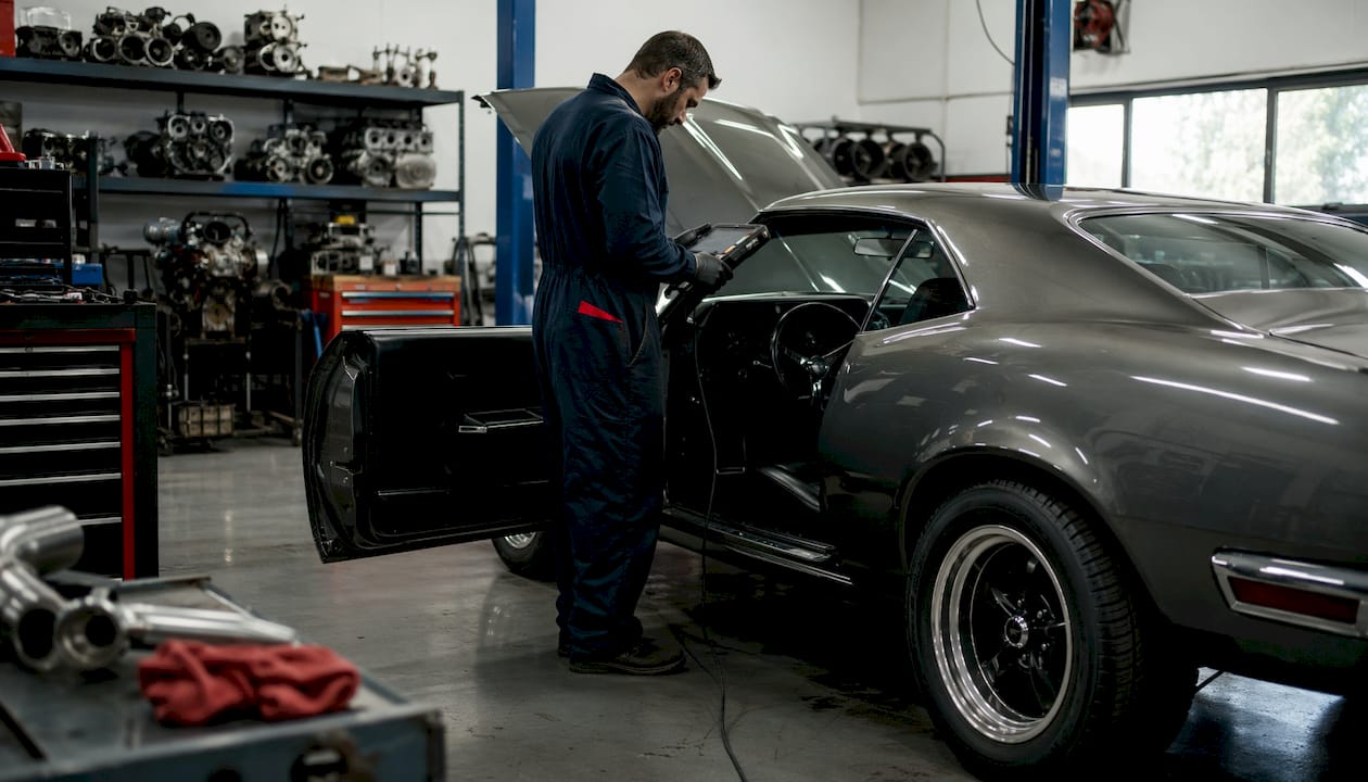
Performance mods commonly trigger codes that are not actual failures. They are flow-change artifacts that need mechanical verification, not parts replacement. Scan tools give you the code; a backpressure gauge and gas analyzer tell you whether the hardware is actually at fault.
Mechanical issues add another layer. A stuck valve, failed actuator, or packaging-caused restriction can look identical to a sensor fault on a scan tool. Only a physical backpressure measurement and a valve-travel check separate the two. Combining scan-tool data with mechanical measurements is the standard that professional shops follow for exactly this reason.
Pro Tip: Capture both a cold baseline and a warm baseline with the valve in its standard open and closed positions before the install. Those two reference points are what make post-install comparisons meaningful.
How to run a diagnostic workflow for a valved exhaust install
Follow this sequence every time. Skipping steps is where misdiagnoses start.
- Baseline logging. With the stock exhaust in place, log wideband AFR, MAF, MAP, and calculated load at idle, steady cruise, and a full-throttle pull. Save the file.
- Pre-start inspection. After install, confirm valve wiring, actuator travel, and linkage movement before any engine start. Check clearances and look for obvious leaks at flanges and joints.
- Static backpressure check. Install a gauge at the O2 bung. Record pressure at idle and at a steady 2,500 rpm. Compare to baseline and known-good ranges for your platform.
- Functional valve check. Cycle the valves through all positions while logging wideband and calculated load. Watch for transient AFR swings or irregular backpressure jumps that track to specific valve positions.
- Dyno pulls. Run controlled, repeatable pulls with consistent inlet conditions. Tune fueling and, where applicable, cam timing or boost to the new flow characteristics. This is also where you confirm the engine response improvements the system is designed to deliver.
- Verification pass. Re-run a combustion check with the gas analyzer or wideband. Confirm no persistent codes remain. If codes persist, follow the interpretation workflow below before replacing any parts.
How to read common diagnostic outputs and avoid misdiagnosis
Fault signatures from valved exhausts follow recognizable patterns. Knowing which pattern points where saves hours of guesswork.
| Reading | Likely Cause | Next Step |
|---|---|---|
| High lambda (lean) at high load | Restriction, boost leak, or fueling issue | Correlate with MAF and calculated load; check backpressure |
| Low lambda (rich) at cruise | Sensor contamination, fueling overcompensation, decaying catalyst | Use gas analyzer to separate O2 vs. HC signals |
| Rising backpressure at steady revs | Physical restriction in pipe, converter, or valve | Quantify with gauge; backpressure at O2 bung is the reliable test |
| P0420 / P0430 codes | Catalyst efficiency drop — but false-positive rates are significant | Run five-step check before replacing |
| Intermittent O2 codes post-install | Valve actuator, wiring fault, or new leak | Inspect valve motor function and connectors first |
The P0420/P0430 false-positive rate is worth pausing on. A five-step check before condemning a converter: live O2 data, misfire check, smoke/leak test, backpressure measurement, and substrate inspection. Skipping any one of those steps and ordering a new converter is an expensive mistake that happens constantly.
Pro Tip: Differentiating a failing MAF from a physical restriction comes down to calculated load. A restriction drops calculated load and shows measurable backpressure at the O2 bung. A MAF fault typically shows abnormal fuel trim without a corresponding backpressure rise.
When can you run these tests yourself, and when should you call a shop?
Some of this is genuinely DIY-friendly. Some of it is not.
- Reasonable for DIY: baseline wideband logging, visual inspection, valve-motor travel checks, and idle backpressure tests using a proper bung adapter.
- Call a performance shop when: backpressure is elevated under load, dyno tuning is required, intermittent codes persist after basic checks, or any test involves removing catalysts or running pressurized smoke tests.
- Safety first: road testing a vehicle with a suspected restriction carries real risk of engine damage, fire, or exhaust-related hazard. Static backpressure testing at idle and 2,500 rpm is always the safer starting point.
Static backpressure testing gives you the restriction data you need without putting the car — or yourself — at risk on the road. Run the static test first. If numbers are out of range, the car does not leave the shop until the cause is confirmed.
How Valvecontrolexhaust validates systems before they reach you
Valvecontrolexhaust runs dyno-tested validation on its systems before listing them, confirming claimed power and sound changes under controlled, repeatable load conditions. That is not marketing language; it means there is a reference dyno sheet behind the product claim.
The brand also publishes a dedicated valve motor testing guide that walks owners and installers through actuator travel checks, electrical verification, and connector inspection. Vehicle compatibility lists are maintained per model, so you know before ordering whether the system fits your Audi, BMW, Ferrari, or Lamborghini application.
Dyno testing under controlled loads and repeated runs is the only practical way to validate claimed power, torque, and valve position behavior for bespoke valved exhaust systems.
CAE simulation tools like GT-POWER, used by major engine manufacturers, can pre-validate exhaust acoustics and pressure dynamics before physical prototypes are built. Valvecontrolexhaust incorporates R&D simulation in its design process, but simulation does not replace a real dyno and backpressure verification for a bespoke valved system on a specific chassis.
Pro Tip: When reviewing a dyno sheet for any valved exhaust, check that pulls were run with the valve in both open and closed positions. A single-position dyno run tells you half the story.
Key Takeaways
Exhaust diagnostic tools work because combining electronic scan data with mechanical measurements (backpressure, gas analysis) is the only way to separate real faults from flow-change artifacts in valved performance systems.
| Point | Details |
|---|---|
| Baseline before you touch anything | Log wideband, MAF/MAP, and calculated load on the stock exhaust before any modification. |
| Combine electronic and mechanical tests | Scan tools give codes; backpressure gauges and gas analyzers confirm whether hardware is actually at fault. |
| P0420/P0430 needs a five-step check | Up to 40% of these codes can be false positives, so never replace a converter without live O2, misfire, smoke, backpressure, and substrate checks. |
| Dyno validates what nothing else can | Repeated controlled pulls with valve positions logged is the only reliable method to confirm power and sound gains. |
| Valvecontrolexhaust provides the reference data | Dyno-validated systems and published valve-motor testing guides give owners and installers a verified starting point. |
What most guides get wrong about exhaust diagnostics
The standard advice is “read the code, replace the part.” That works fine on a stock commuter car. On a valved performance exhaust, it is almost always wrong.
The real issue is that valved systems introduce a moving variable. Backpressure, flow velocity, and sensor exposure all change with valve position, and most scan tools have no idea which position the valve was in when the code was stored. That context gap is where misdiagnoses live. A P0420 on a Ferrari 458 with an aftermarket valved system is not the same diagnostic problem as a P0420 on a stock sedan. Treating them identically wastes money and time.
The other thing guides consistently underweight is record keeping. Log engine coolant temp, valve position, gear, and rev range during every test run. Without those variables, you cannot reproduce the condition that triggered the fault, and you cannot prove the fix worked. A gas analyzer that has not reached operating temperature will give you bad lambda readings. A wideband logged in closed-loop at light throttle tells you almost nothing about high-load behavior. These are the details that separate a clean diagnostic from an expensive guess.
Valvecontrolexhaust: dyno-tested systems built for your build
If you want a valved exhaust system where the diagnostic work has already been done, Valvecontrolexhaust is the direct answer. Every system ships with dyno-validated performance data, documented actuator testing procedures, and model-specific compatibility confirmation for platforms like Audi, BMW, Porsche, Ferrari, Lamborghini, and Mercedes-AMG.

What you get when you order from Valvecontrolexhaust:
- Dyno validation: confirmed power and sound data from controlled test runs
- Actuator testing documentation: step-by-step valve motor and wiring verification guides
- Installer guidance: technical resources for shops and informed owners
- Model compatibility: verified fitment lists so there are no surprises on install day
- Tech support: access to troubleshooting resources for valve-specific fault diagnosis
Explore the full range of customizable exhaust systems and find the right fit for your vehicle, or check the luxury car exhaust benefits page to see what a properly validated valved system actually delivers.
Authoritative sources used in this article
| Source | What It Backs |
|---|---|
| Walker Exhaust: OBD Basics | Check Engine light as a warning, not a diagnosis; OBD-II monitoring scope |
| MOTOR: Turn On Your Exhaust Analyzer | Gas analyzer value; combined scan-tool + mechanical diagnostic approach |
| Tire Review: Exhaust Restriction Diagnosis | Backpressure testing at O2 bung; calculated load vs. MAF differentiation |
| Steer.so: Catalytic Converter Diagnosis | P0420/P0430 false-positive rate; five-step diagnostic workflow |
| G-W Safety Chapter | Road-test safety risks; static backpressure testing as safer alternative |
| Modern Exhaust Diagnostics Review | FTIR/NDIR spectroscopic methods; continuous monitoring and ML-based fault detection |
| Valvecontrolexhaust: Dyno Testing Guide | Dyno validation as the standard for bespoke valved exhaust performance claims |