
Exhaust valve wiring is defined as the electrical system that connects your vehicle’s ECU to an actuator, controlling valve position in real time to manage exhaust flow, sound, and backpressure. The ECU sends pulse-width modulation (PWM) signals commanding the actuator to rotate between 0° and 90°, while simultaneously monitoring current draw and return voltage to confirm the valve responded correctly. Understanding how exhaust valve wiring works is the foundation for any serious exhaust modification on performance vehicles like BMW, Audi, Ferrari, or Lamborghini. Get the wiring wrong and you lose drive modes, trigger fault codes, or lock your exhaust permanently open.
How exhaust valve wiring works: the core electrical loop
The wiring circuit in an active exhaust system does two jobs at once. It delivers power to the actuator and sends data back to the ECU. Wiring acts as a data channel, not just a power supply. That distinction matters more than most DIY modifiers realize.
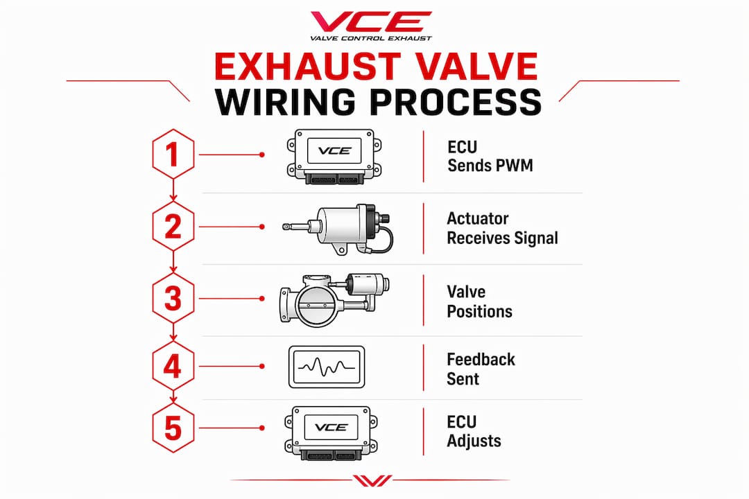
The ECU generates a PWM signal, which is a rapid on-off pulse whose duty cycle determines valve position. A 10% duty cycle holds the valve nearly closed. A 90% duty cycle pushes it fully open. The actuator, whether a DC motor or solenoid, translates that signal into physical rotation across the 0° to 90° arc.
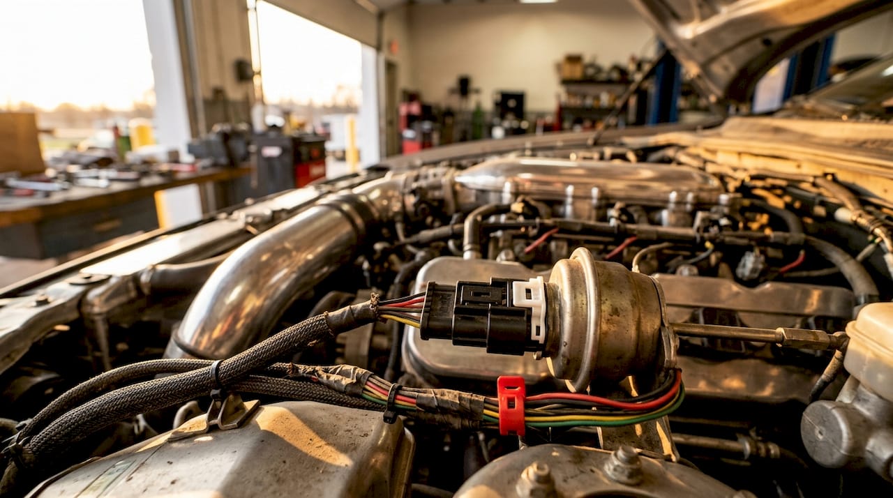
Simultaneously, the ECU reads the actuator’s current draw and return voltage. If those values fall outside the expected range, the ECU flags a fault. Fault codes are logged within 1 to 3 ignition cycles when an open circuit appears in the wiring. That speed means a loose connector can kill your sport mode before you reach the end of your driveway.
The ECU also uses this feedback loop to adjust valve position dynamically based on engine load, RPM, and throttle position. This is why exhaust valve control feels responsive rather than binary. The valve is not simply open or closed. It holds intermediate positions to balance sound and flow at every point in the rev range.
What types of actuators are used and how do they change the wiring?
Two main actuator types exist in active exhaust systems: vacuum-actuated and electric motor driven. Each demands a different wiring approach.
Vacuum-actuated systems
Vacuum systems use a solenoid valve wired to the ECU. The solenoid controls airflow through vacuum lines, which physically move a diaphragm to open or close the exhaust valve. The wiring itself is relatively simple, carrying only the on/off signal to the solenoid. The complexity lives in the vacuum plumbing, not the harness.
The downside is response time. Vacuum pressure builds and drops slowly compared to an electric signal. That lag shows up as a slight delay between your throttle input and the exhaust note change.
Electric motor and solenoid actuators
Electric actuators use small DC motors driven directly by PWM signals from the ECU. The wiring harness carries both the command signal and the feedback circuit. Electric servo motors provide faster response and eliminate vacuum lines entirely, but they demand a more complex wiring setup with dedicated feedback wires.
| Feature | Vacuum-actuated | Electric motor |
|---|---|---|
| Wiring complexity | Low (on/off signal) | High (PWM + feedback) |
| Response speed | Slower | Faster |
| Vacuum lines required | Yes | No |
| Feedback circuit | None | Current and voltage |
| Common on | Older platforms | Modern performance cars |
Key differences that affect your DIY wiring job:
- Vacuum systems need a solenoid wired in-line and vacuum lines routed away from heat
- Electric systems require a multi-pin connector carrying signal, ground, power, and feedback
- Electric actuators are sensitive to wiring resistance, so connector quality matters significantly
- Swapping actuator types without rewiring the harness causes immediate ECU faults
How does the ECU communicate with the actuator through the wiring?
The ECU treats the exhaust actuator wiring as a closed-loop control system. It sends a command and expects a specific electrical response. If the response does not match, it acts.
PWM signals command valve position with precision. The duty cycle changes continuously as the engine moves through different operating states. At idle, the valve stays mostly closed to keep the exhaust quiet. Under hard acceleration, the ECU opens the valve to reduce backpressure and increase flow. The wiring carries these changes in real time, hundreds of times per minute.
The ECU monitors two return signals through the wiring:
- Current draw: A healthy actuator draws a predictable amount of current. A spike indicates a mechanical jam. A drop to zero indicates a broken wire or disconnected connector.
- Return voltage: The ECU reads the voltage at the actuator terminal to confirm the signal arrived and the actuator responded.
ECU monitoring of actuator resistance and current draw via wiring maintains system status continuously. This is why the system catches faults so fast.
Drive mode integration adds another layer. When you select Sport or Track mode on a BMW M car or a Lamborghini Huracán, the ECU sends a different PWM profile to the exhaust actuator. The wiring carries that mode-specific command. If the wiring is degraded, the actuator cannot respond correctly, and the ECU may block access to those modes entirely as a safety measure.
Pro Tip: Use an OBD2 scanner with bidirectional control to command the exhaust valve open and closed while listening for the actuator click. Scanners like Autel MaxiCOM and Foxwell NT510 support this function and can confirm whether a fault lives in the wiring or the actuator itself.
What are best practices for wiring exhaust valves on a DIY build?
Wiring exhaust valves correctly requires treating the harness like a precision component, not an afterthought. Heat, vibration, and moisture are the three enemies of every connector under your car.
Follow this sequence when wiring or rewiring exhaust valve actuators:
- Use Teflon-coated wire. Military-grade Teflon-coated wiring and waterproof connectors resist the heat cycles and moisture that destroy standard automotive wire over time.
- Route away from exhaust pipes. Keep wiring at least 50mm from any exhaust surface. Use heat-resistant conduit or loom where routing forces proximity to the pipe.
- Secure every 150mm. Zip-ties or P-clips prevent vibration from fatiguing the wire at connector entry points, which is where most breaks occur.
- Inspect connectors before closing the job. Corroded or bent pins cause intermittent faults that are harder to diagnose than a clean open circuit.
- Test with a bidirectional scanner before driving. Confirm the ECU sees the actuator and can command it before you put the car on the road.
If you remove the physical exhaust valve entirely, you must address the wiring circuit. Simply unplugging the connector triggers fault codes within 1 to 3 ignition cycles and can lock out sport or track modes. An exhaust valve simulator solves this by replicating the actuator’s electrical resistance and feedback signal. Simulators prevent CEL activation and keep drive modes fully functional.
Mount simulators away from the exhaust. Heat degrades simulator electronics and causes intermittent fault codes even when the wiring itself is perfect. A bracket mounted to the chassis, not the exhaust hanger, is the right location.
For troubleshooting valve wiring, always start at the connector. Pull it, inspect the pins, and measure resistance across the actuator terminals before chasing the harness back to the ECU.
How does wiring quality affect exhaust valve performance?
Wiring quality directly determines whether your exhaust system performs as designed. A degraded harness does not just cause fault codes. It changes how the valve behaves under load.
The ECU adjusts valve position dynamically based on three engine parameters: load, RPM, and throttle position. If wiring resistance increases due to corrosion or a poor splice, the PWM signal arrives at the actuator with reduced amplitude. The actuator may not reach its commanded position. The result is a valve that opens partially when it should open fully, reducing the performance benefit at high RPM.
| Wiring condition | ECU behavior | Driver experience |
|---|---|---|
| Clean, low resistance | Full PWM range delivered | Correct valve response across all modes |
| Corroded connector | Reduced signal amplitude | Partial valve opening, muted sound |
| Open circuit | Fault code logged in 1–3 cycles | Loss of sport/track modes |
| Short to ground | Immediate fault, possible actuator damage | Valve locked in one position |
Wiring transmits feedback signals that the ECU uses for dynamic exhaust management. When you install an aftermarket actuator or simulator, matching the electrical resistance of the factory unit is not optional. The ECU expects a specific resistance value. A mismatch reads as a fault even if the physical connection is solid.
The performance implications extend to variable valve exhaust systems, where the valve holds dozens of intermediate positions rather than toggling between open and closed. That level of control depends entirely on clean, low-resistance wiring delivering accurate PWM signals.
Key Takeaways
Exhaust valve wiring is a closed-loop control system where the ECU sends PWM signals, monitors actuator feedback, and adjusts valve position dynamically based on engine load and RPM.
| Point | Details |
|---|---|
| ECU sends PWM signals | Duty cycle controls valve position between 0° and 90° in real time. |
| Feedback loop is critical | ECU monitors current draw and voltage to detect wiring faults within 1–3 ignition cycles. |
| Actuator type changes wiring | Electric actuators need multi-pin feedback harnesses; vacuum systems use simpler on/off solenoid wiring. |
| Wiring quality affects performance | Corroded or high-resistance wiring reduces signal amplitude and causes partial valve opening. |
| Simulators protect ECU integrity | Exhaust valve simulators replicate factory resistance to prevent fault codes after valve removal. |
Why I think most DIYers underestimate the wiring side of exhaust mods
Most exhaust modification guides focus on the pipe, the tip, and the sound. The wiring gets a paragraph, maybe two. That is backwards. The wiring is where the modification either succeeds or quietly fails over the next six months.
The most common mistake I see is treating the actuator connector like a light switch. Unplug it, delete the valve, move on. The ECU does not move on. It logs a fault, restricts drive modes, and in some cases limits engine output as a precaution. The car becomes less capable because of a connector that took 30 seconds to remove.
Simulators are the right answer for most valve-delete builds. They are not a workaround. They are the correct engineering response to removing a component the ECU expects to see. The key is mounting them correctly and matching the factory resistance spec. Get those two things right and the ECU never knows the physical valve is gone.
The other thing worth saying directly: Teflon-coated wire and waterproof connectors are not upgrades. They are the minimum standard for anything running near an exhaust system. Standard automotive wire degrades faster than you expect in that environment. Use the right materials from the start and you will not be chasing an intermittent fault code six months later.
Understanding the wiring also helps you use your exhaust valve motor testing tools correctly. A bidirectional scanner tells you exactly where the fault lives. That knowledge saves hours of unnecessary disassembly.
— Info
Valvecontrolexhaust products for exhaust valve wiring and simulation
Valvecontrolexhaust builds exhaust valve simulators designed to replicate the factory actuator’s electrical resistance and feedback signal exactly. The result is a clean ECU read with no fault codes and no loss of drive modes after valve removal.

Every simulator Valvecontrolexhaust produces is engineered for the specific resistance and signal profile the ECU expects on platforms like Audi, BMW, Ferrari, and Lamborghini. Installation guides cover wiring routing, connector protection, and heat-safe mounting locations. For enthusiasts who want to go deeper before buying, the performance exhaust system analysis covers how valved systems compare across the full range of high-performance builds. Valvecontrolexhaust also provides direct support to help you confirm compatibility and wiring specs before you start cutting anything.
FAQ
What signal does the ECU use to control an exhaust valve?
The ECU uses a pulse-width modulation (PWM) signal to command the actuator, varying the duty cycle to position the valve between 0° and 90°.
How fast does the ECU detect a wiring fault on an exhaust valve?
The ECU logs a fault code within 1 to 3 ignition cycles when it detects an open circuit or missing feedback signal from the exhaust valve wiring.
Can I just unplug the exhaust valve connector to delete the valve?
Unplugging the connector triggers fault codes quickly and can lock out sport or track drive modes. An exhaust valve simulator is the correct solution.
What wiring type should I use near exhaust components?
Military-grade Teflon-coated wire with waterproof connectors is the correct choice. Standard automotive wire degrades rapidly under the heat and vibration near exhaust pipes.
How do I test exhaust valve wiring without removing the actuator?
Use an OBD2 scanner with bidirectional control, such as the Autel MaxiCOM or Foxwell NT510, to command the valve and listen for actuator response while monitoring live ECU data.